
You will then be prompted to Choose Second 3D Object or Face.

These types of clearance violations can then be displayed and resolved in 3D measuring tools.ģD measurement clearance checking design rules are great, but an equally important aspect of design is ensuring that clearances are correct.

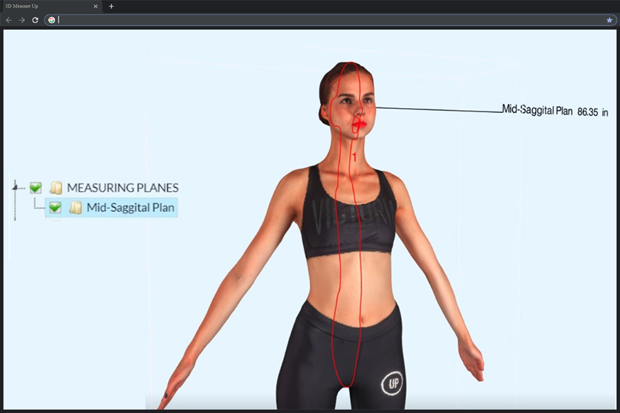
This includes clearance between 3D models used to define extruded or simple types of component bodies. The component clearance Circuit Board design rule specifies the minimum distance that components can be placed from each other. While other programs may include a tool to measure distance from one component body to another, Altium Designer 3D measurement can measure the distance from one object to another, from a single face to another single face, an object to the board, and even cross-probing of multiple measurement results.Īltium Designer includes extensive PCB design rule checking, including a component clearance rule that can be configured to keep your components from colliding or coming within a specified distance from each other on all three axes. The Altium Designer 3D measurement tool also includes several other advanced features that separate it from other ECAD tools. The Native 3D PCB editor gives the designer not only a highly realistic view of what the fully assembled board will look like, but also the ability to perform critical PCB design software tasks, such as 3D clearance checking, examining the location and presentation of text strings, inspecting each individual 3D layer within a single layer mode, and even performing measurements directly within 3D.


 0 kommentar(er)
